Why switched grounds?

WDD

Final Approach
PoA Supporter
Joined
Oct 16, 2019
Messages
6,072
Location
Atlanta / Marietta
Display Name

Display name:
Vintage Snazzy (so my adult children say)
I'm noticing that electrical switches in planes are "switched grounds". That is, the positive side of the battery is flowing to the electronics, lights, whatever. The only thing stopping the circuit from completing is a ground, which is what the switch controls.

I would have thought the circuit would be controlled by blocking the current from getting to the electronics, etc. in the first place, and the ground would have been hard wired. That way an errant ground wouldn't complete the circuit. Many things can be a ground, but only a wire carrying current can provide the power.

It surely is done this way for a good reason, but I can't figure out what that reason would be.
 
It surely is done this way for a good reason, but I can't figure out what that reason would be.
In very general terms, it depends in how they want the circuit control to fail when it does. And these circuits are usually referred to as ground seeking vs power seeking systems. However, there are many variations to this depending on system and design.
 
"Grounds" are everywhere. Hots are usually run individually. It's often more convenient to short the load to ground as a switch than it is to put a switch on the hot side.
 
I'm noticing that electrical switches in planes are "switched grounds". That is, the positive side of the battery is flowing to the electronics, lights, whatever. The only thing stopping the circuit from completing is a ground, which is what the switch controls.
Certainly in the majority of GA aircraft and circuits I've worked on with aircraft they are switched power. The most common switched ground is for your master switch (mostly because there is no power to switch until the master contactor is closed). But in general, I think you'd find most are switched power (lighting, avionics busses, pitot heat, etc). Part of the reason for that is weight, as in metal aircraft things are generally grounded relatively locally, to avoid the additional weight of having to run two sets of wires and the airframe is used as the ground path. But of course, that is a generality, and there are usually reasons for why one circuit might be done one way, and another done differently. Out of curiosity, do you have an example of where you are seeing lots of switched grounds?
 
Certainly in the majority of GA aircraft and circuits I've worked on with aircraft they are switched power. The most common switched ground is for your master switch (mostly because there is no power to switch until the master contactor is closed). But in general, I think you'd find most are switched power (lighting, avionics busses, pitot heat, etc). Part of the reason for that is weight, as in metal aircraft things are generally grounded relatively locally, to avoid the additional weight of having to run two sets of wires and the airframe is used as the ground path. But of course, that is a generality, and there are usually reasons for why one circuit might be done one way, and another done differently. Out of curiosity, do you have an example of where you are seeing lots of switched grounds?

That has been my observation as well. I’m left wondering where all these switched grounds are, as I’ve seen relatively few in the light airplanes and helicopters I work on.
 
Certainly in the majority of GA aircraft and circuits I've worked on with aircraft they are switched power. The most common switched ground is for your master switch (mostly because there is no power to switch until the master contactor is closed). But in general, I think you'd find most are switched power (lighting, avionics busses, pitot heat, etc). Part of the reason for that is weight, as in metal aircraft things are generally grounded relatively locally, to avoid the additional weight of having to run two sets of wires and the airframe is used as the ground path. But of course, that is a generality, and there are usually reasons for why one circuit might be done one way, and another done differently. Out of curiosity, do you have an example of where you are seeing lots of switched grounds?
The avionics guy was telling me my avionics master switch relay was a ground switch.

Perhaps I assumed wrongly that other switches were similar.

Always learning new things here.
 
Which end of the circuit is the breaker on? Maybe having a way to open the circuit on both sides would be advantageous. :dunno:
 
The avionics guy was telling me my avionics master switch relay was a ground switch.

Perhaps I assumed wrongly that other switches were similar.

Always learning new things here.
The other electrical items are usually grounded adjacent to where they are located, having a switched ground would defeat the purpose of using the airframe as ground.
 
The other electrical items are usually grounded adjacent to where they are located, having a switched ground would defeat the purpose of using the airframe as ground.
How so?
 
Because then you'd either have to have the switch very close to each load to be in-between the short run from the load to the local ground (impractical/inconvenient for the pilot), or else run all the grounds back to a common switch panel which...defeats the purpose of using the airframe as ground.
 
Always learning new things here.
In reality, the only time an electrical circuit is grd vs power switched or is grd seeking vs power seeking becomes relevant at the pilot/mechanic level is when troubleshooting a problem with that circuit. And especially with electrical systems that have complex control logic where downstream components may use a combination of those traits by design.
 
The avionics guy was telling me my avionics master switch relay was a ground switch.

Perhaps I assumed wrongly that other switches were similar.

Always learning new things here.
Avionics master controls a relay. The relay is normally closed, so if it fails, you still have your avionics. So the switch may be a switched ground as in operation, it is open.
 
Lets consider just 2 circuits where switching ground makes sense.

I am not looking at any specific manufacturer drawing.

The master solenoid is located as close as possible to the battery. A small hot wire from the battery goes directly to a nearby small fuse, then to the coil of the master contactor. On the other side of the master contactor, a terminal from the coil is connected to a wire, through the firewall, to the master switch, which when turned on, connects the circuit to ground, and the master contactor is energized, and "hot" DC is sent to the DC buss and its connected "hot" switches.

In flight, with all the vibration normal for that condition, if the switched ground wire of the master contactor rubs through its insulation, and becomes grounded, the pilot is unaware of any problem, every thing continues to work. The first he does become aware is when he shuts down on the ground at an airport, and the master switch does not shut off anything. This is a relaxed, and safe, time to find the problem. Technicians may be available to help.

If that small wire from the small fuse at the battery went through the firewall to the master switch, then back through the firewall to the solenoid coil, either of those passes through the firewall becoming grounded would blow the fuse at the battery, and shut down ALL the electrical devises except the magnetos.

Modern electronics do have internal batteries, and would continue to function for a limited time. Trivial things such as panel lights and landing lights at night, flaps, landing gear on many planes, comm receivers and transmitters, transponders, ADSB, and many more would be lost, and no way to replace the fuse until on the ground.

The electronics master may also be wired ground switched for the same reason.

Those are the only devices that should normally be wired with switched ground. They are also the only circuits normally fused right at the battery.

I believe Pinecone is incorrect, the avionics master is not normally de energized, as that would mean that it would need to be energized when the plane is parked, or, the individual electronics devices would need to be turned off when the plane is parked. Our planes used the avionics master to turn on or off all the avionics at the same time.

If I am incorrect, Dan Thomas will correct me.
 
Because then you'd either have to have the switch very close to each load to be in-between the short run from the load to the local ground (impractical/inconvenient for the pilot), or else run all the grounds back to a common switch panel which...defeats the purpose of using the airframe as ground.
That's only part of the reason. More to the point, you don't want to have different ground impedances for different devices, particularly avionics. Ground is the "universal" voltage reference, so you want each and every device to have the lowest possible impedance (resistance) to ground, so that they all are operating on the same exact 0V reference point.

Adding in a long[ish] wire and switch contact to the ground connection would add both resistance and inductance, which means that the ground reference would no longer be 0V, but some slightly higher level -and different from every other device. To make matters worse, as the current draw increases, the voltage lift increases, as well (V=IR in DC circuits).

Now, imagine if you have your GPS "grounded" at 0.3V, but your G-5 in the panel is at 0.5V, and your radios are at 0.7V. That will create all sort of noise and communications problems...and be nearly impossible to find if you don't understand the problem.
 
The avionics guy was telling me my avionics master switch relay was a ground switch.

Perhaps I assumed wrongly that other switches were similar.
You may wish to find a service manual for your particular ride - there should be schematics in there so you can see what circuits have switched power and which have switched grounds.
I suspect most have switches on the power side. Some things like the micro switches for gear indicator lights may be on the ground side because you only have to run one wire between the light and the switch (the lights are close to power under the panel, and the switches are close to grounds under yea olde winge).
 
Grumman was a believer in switched grounds. So much so that the early G II's the battery switch was a ground for the whole airplane. And it was placed right next to the emergency inverter switch with no guard. So when you turned it off you had an electrically dead airplane. Caused a couple crashes when pilot went for inverter switch and turned all power off.
 
Fun fact: If you have an older vehicle with a generator (not alternator) and no radios, it doesn't matter if you connect the battery positive or negative to ground.
 
When using solid state switches, it is easier, cheaper and simpler to switch grounds instead of power. The power transistors used for the switching have better performance when built in the ground switching configuration.
 
The master solenoid is located as close as possible to the battery. A small hot wire from the battery goes directly to a nearby small fuse, then to the coil of the master contactor.
No fuse. Never have I ever seen a fuse in that wire. There are fuses near the battery for the clock and hourmeter, but they are not related to the master circuit. A fuse there will eventually fail though simple corrosion, and leave the pilot with a dead system for no good reason. The master contactor is located right next to the battery to keep unfused wiring as short as possible, and clear of anything that might short it.

I've never seen switched grounds in any light airplane other than the master circuit. All switches are connected to the relevant breaker, which is connected to the bus, which is battery positive from the master contactor. One exception is often the avionics master, which is just a switch to disconnect the avionics bus from the main bus. Some airplanes used a small relay for that purpose, controlled by the avionics master switch.

That master is wired the way it is for good reason. The master switch on the panel grounds the master contactor's coil, whose other end is hot. This avoids having a hot wire from the battery into the cockpit to that switch. A wire that's always hot could short during an accident even if the master was off, causing sparks that could set spilled fuel afire. The method of grounding the contactor to turn it on means that there will always be a considerable resistance in that line, the resistance of the coil, and so if the the master is turned off and the airplane crashes, tearing and shorting that wire just turns the master on. It doesn't make huge sparks or get wiring glowing red-hot.

We've all been taught to turn the master off in a forced approach, right??

1726069898899.png

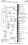
From a 172 service manual, the battery/master/starter circuit:

1726070947872.png

#2 is the master switch. #5 is a diode that shorts the voltage spike from the master contactor's coil. #1 is another diode that suppresses the voltage spike from the alternator circuit. #7 is the master contactor, here labelled the "battery contactor." The starter is #11. Battery is #6. #4 and #5 are just the two halves of a connector.

The power for the bus comes off that little circle just to the right of the battery contactor, in the line to the starter contactor. That's the output stud of the contactor. Note the absence of any fuses in the wires labelled PA25 and PA24 to the master switch.
Sometimes that bus line will be taken off the starter contactor's input terminal, which amounts to the same thing. This will be done in airplanes having the battery back in the tailcone.

Here is an example of load switching, the landing lights:

1726071624947.png

The switches are in the line from the bus, via the circuit breaker. The lights are fed positive into one terminal, and the other is grounded to the negative airframe.

One more, the ammeter:


1726071899889.png

We find it in that line from the starter contactor's input terminal from the battery contactor (or from the battery contactor's output terminal, same thing) and through the ammeter to the bus bar. No fuses anywhere in that line. If it shorts, you get smoke and stuff and you shut the master off. Fuses, again, introduce more risk that they eliminate in such a system. That fuse would be really big, too, and would have to be accessible in flight. In the way things are wired, the pilot is the fuse. If he's smart. The POH/AFM tells him all about it, if he cares to know.

That ammeter tell the pilot how much power is leaving or entering the battery. If the battery is discharging, it will read so. If the alternator or generator is charging, it will show a charge. It will show how much flow is going in either direction. Note the that starter current does not travel through the ammeter. 60-amp ammeters don't appreciate having 250 amps run through them.
 

Attachments

  • 1726070328869.png
    1726070328869.png
    199.9 KB · Views: 3
Fun fact: If you have an older vehicle with a generator (not alternator) and no radios, it doesn't matter if you connect the battery positive or negative to ground.
It would really be fun if you have a permanent magnet starter installed. Not to mention any catch diodes placed across relay/contactor coils.
 
As always, Dan has the wiring diagrams to prove his points.
Mine were donated when I downsized to an apartment.

He has tweaked my memory, and yes, that fuse by the battery is the clock. Thank you, Professor Thomas.

The switched ground for the master solenoid is called "Fail safe" engineering.

Flying Brit, in the old DC generator days, there were no permanent magnet starters.

Super magnets were invented by Norman Koon over Labor day at Bethany Beach, Delaware. He filed for a patent on September 6, 1985. Patent granted August 6, 1985.

He was working on his laptop at the same table as I was reading a book. Our wives and kids were at the beach, and I had all the sun that was good for me He looked at me, and stated, I have found the answer, I am going back to the office to document it. When my wife and kids come back from the beach, tell her I went back. Someone else here can give them a ride home tomorrow. He did not even go to their room for his suitcase, just out to his car, and gone.
 
It would really be fun if you have a permanent magnet starter installed. Not to mention any catch diodes placed across relay/contactor coils.
If the vehicle is old enough to have a generator, it's not going to have a permanent magnet starter.
 
See last 2 paragraphs by Geezer, just above.

The dates may be for the wrong patent, as he had 6 patents related to super magnets. He worked for the Navy, the Secretary of the Navy was the assigned patent holder for most of his patents.
 
Last edited:
Because then you'd either have to have the switch very close to each load to be in-between the short run from the load to the local ground (impractical/inconvenient for the pilot), or else run all the grounds back to a common switch panel which...defeats the purpose of using the airframe as ground.
I'm still not following. It's exactly the opposite. If the switch is not near either the load or the + source, then switching to "ground" minimizes wire. This is why it is done. It's not even limited to aircraft. Cars do this all the time as well. Run a single wire the bus to the load and then to the switch and the ground rather than wire from bus to switch to load to ground.
 
I'm still not following. It's exactly the opposite. If the switch is not near either the load or the + source, then switching to "ground" minimizes wire. This is why it is done. It's not even limited to aircraft. Cars do this all the time as well. Run a single wire the bus to the load and then to the switch and the ground rather than wire from bus to switch to load to ground.
The switches are usually really close to the bus. The load is usually really far from both.
 
I remember when I was a young lad and still "learning" my mechanical aptitude skills I was working on my Ford F-250 and I had to move the alternator out of the way. Thing is I forgot to disconnect the battery and when I popped the alternator out of it's bracket it firmly wedged itself between the body and frame with the terminal being one of the contact points. That's the day I found out what a fuseable link was. It made a ghostly howling sound for about ten seconds and a whole bunch of smoke.
Probably saved my truck though.
 
I'm still not following. It's exactly the opposite. If the switch is not near either the load or the + source, then switching to "ground" minimizes wire. This is why it is done. It's not even limited to aircraft. Cars do this all the time as well. Run a single wire the bus to the load and then to the switch and the ground rather than wire from bus to switch to load to ground.
Draw out a circuit to feed the tail strobe using switched grounding.
 
I'm still not following. It's exactly the opposite. If the switch is not near either the load or the + source, then switching to "ground" minimizes wire. This is why it is done. It's not even limited to aircraft. Cars do this all the time as well. Run a single wire the bus to the load and then to the switch and the ground rather than wire from bus to switch to load to ground.
There are lots of ways to skin a cat.

The way the cat is skinned in my plane, there's a big fat + wire that goes through a 60A cb in the front panel. Another fat wire connects the output of that 60A cb through a relay to a bus bar from which multiple + wires each go through smaller individual cbs and then make a short run to a bank of switches and knobs located only a few inches away.

The output of those switches are long + wires that run to:
lights on the wingtips​
lights on the front of the cowling​
a fuel pump under the cowling​
lights on the top and backside of the tail​
pitot heat halfway down the wing​

On the other side of those loads, a short wire connects directly to nearby metal structure, which provides a return path to "ground".

Your plane and car (and even some loads in my plane) may be wired differently, but it should not be hard to follow why sometimes this method of wiring is used.
 
Your plane and car (and even some loads in my plane) may be wired differently, but it should not be hard to follow why sometimes this method of wiring is used.
Cars might be doing it differently, but they have a lot of plastic body panels now. Those don't work too well for ground paths.

The big problems with switched grounds is that the wire to the load is hot all the time the master is on and, as has been noted, a long return ground line is necessary for remote loads. The only advantage I can see there is the elimination of electrical ground loops that cause audio noise. The extra weight and complexity are not welcome.
 
Any and every electric or electronic part can be made into a smoke generator if you operate it wrong enough.
 
Back
Top