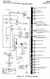
The master solenoid is located as close as possible to the battery. A small hot wire from the battery goes directly to a nearby small fuse, then to the coil of the master contactor.
No fuse. Never have I ever seen a fuse in that wire. There are fuses near the battery for the clock and hourmeter, but they are not related to the master circuit. A fuse there will eventually fail though simple corrosion, and leave the pilot with a dead system for no good reason. The master contactor is located right next to the battery to keep unfused wiring as short as possible, and clear of anything that might short it.
I've never seen switched grounds in any light airplane other than the master circuit. All switches are connected to the relevant breaker, which is connected to the bus, which is battery positive from the master contactor. One exception is often the avionics master, which is just a switch to disconnect the avionics bus from the main bus. Some airplanes used a small relay for that purpose, controlled by the avionics master switch.
That master is wired the way it is for good reason. The master switch on the panel grounds the master contactor's coil, whose other end is hot. This avoids having a hot wire from the battery into the cockpit to that switch. A wire that's always hot could short during an accident even if the master was off, causing sparks that could set spilled fuel afire. The method of grounding the contactor to turn it on means that there will always be a considerable resistance in that line, the resistance of the coil, and so if the the master is turned off and the airplane crashes, tearing and shorting that wire just turns the master on. It doesn't make huge sparks or get wiring glowing red-hot.
We've all been taught to turn the master off in a forced approach, right??

From a 172 service manual, the battery/master/starter circuit:

#2 is the master switch. #5 is a diode that shorts the voltage spike from the master contactor's coil. #1 is another diode that suppresses the voltage spike from the alternator circuit. #7 is the master contactor, here labelled the "battery contactor." The starter is #11. Battery is #6. #4 and #5 are just the two halves of a connector.
The power for the bus comes off that little circle just to the right of the battery contactor, in the line to the starter contactor. That's the output stud of the contactor. Note the absence of any fuses in the wires labelled PA25 and PA24 to the master switch.
Sometimes that bus line will be taken off the starter contactor's input terminal, which amounts to the same thing. This will be done in airplanes having the battery back in the tailcone.
Here is an example of load switching, the landing lights:

The switches are in the line from the bus, via the circuit breaker. The lights are fed positive into one terminal, and the other is grounded to the negative airframe.
One more, the ammeter:

We find it in that line from the starter contactor's input terminal from the battery contactor (or from the battery contactor's output terminal, same thing) and through the ammeter to the bus bar. No fuses anywhere in that line. If it shorts, you get smoke and stuff and you shut the master off. Fuses, again, introduce more risk that they eliminate in such a system. That fuse would be really big, too, and would have to be accessible in flight. In the way things are wired, the pilot is the fuse. If he's smart. The POH/AFM tells him all about it, if he cares to know.
That ammeter tell the pilot how much power is leaving or entering the battery. If the battery is discharging, it will read so. If the alternator or generator is charging, it will show a charge. It will show how much flow is going in either direction. Note the that starter current does not travel through the ammeter. 60-amp ammeters don't appreciate having 250 amps run through them.


