Anomalous Ammeter Readings + Loss of Alternator

Updates: (and thank you to all who continue to parse through this and offer suggestions :) )

Did another test flight today and couldn't get the alternator to fail. Amps/Voltages looked the same as yesterday's reported values.

Following the test flight I spent the next several hours verifying every electrical line I could think of in the aircraft. Cowl off, seats out, got up under the panel with bright lights + telescoping mirrors and lots of photos.

ENGINE COMPARTMENT WIRES:
This is the area where I found stuff I didn't like.

When the alternator got rewired at annual I think the cables from the alternator got moved down so now they're resting directly on the exhaust pipes from the engine. From my own diagnosis the wires look like they're not doing great down there.
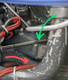
There's some black gunk building up under the black shielded cable (the bigger wire / lower gauge line), and the smaller white cable appears to be a bit dirty and also with some brown marks (burns?).

mirror reflection, brown marks on the white line look like burns? (if it is, not sure if from heat or electrical load)
1718582435196.png
1718582486060.png

There's some black crud building right where the black shielded (big) wire is resting on the exhaust. Is it from the heat? Or rubbing against it and causing chaffing/friction? Combo of both?
1718582588832.png


Here's the big/small wires coming off the alternator itself
1718582627117.png

Most sections of the wire near the engine compartment look a little dirty/aged, but I do not see any exposed wire.
1718582678028.png

Couple spots where its worn through the shielding by the ties but wire insulation still looks fully intact.
1718582729473.png

INTERIOR WIRES:
From what I could tell the interior wires all seemed to have good, sturdy, shielded connections to their terminals. It's complicated as all hell back there, but every wire seemed to be firmly attached and in good condition (1 exception).
Also I found a couple links from the breaker box that don't seem to line up with the component they're hooked up to. I have to investigate that a bit more. I'm going to look at these a bit more in my photos before I post.
 
Agree - nothing should ever be in contact with the exhaust. Not sure that is the cause of your issue, but you should definitely fix that. Did you say that your aircraft just came out of Annual? If so, I am troubled that it wasn’t found then…
 
Agree - nothing should ever be in contact with the exhaust. Not sure that is the cause of your issue, but you should definitely fix that. Did you say that your aircraft just came out of Annual? If so, I am troubled that it wasn’t found then…
Well... It just came out of annual and during annual the shop reinstalled the alternator with a new bracket and changed the wiring.

I brought the plane back with my alternator troubles and they reverified the lines are OK last week. So there's been eyes repeatedly on these lines specifically over the last 1-2 weeks, I don't think it's an oversight so much as an intentional wiring layout which they might have thought was better.

I'm not sure if this is the root cause, but I don't think it's helping matters any. The issue I experience occurs during high power settings at takeoff/climbout, which means lots of heat. So correlation is there, we'll have to find out empirically if it's the causation too.
 
Last edited:
The output cable on the alternator looks rather stressed. If possible, I'd try flipping it 180 degrees so the cable approaches from beneath.

What did the annual and alternator work cost? (rhetorical question) Regardless, it was too much.
 
Those look like intake pipes to me (the 2nd and 3rd pictures), not exhaust (can see the chipped up gray paint), not that it should be in contact with those either for chaffing reasons, but at least they shouldn't be red hot.
 
Those look like intake pipes to me (the 2nd and 3rd pictures), not exhaust (can see the chipped up gray paint), not that it should be in contact with those either for chaffing reasons, but at least they shouldn't be red hot.
You're correct that they're intake pipes. But where I couldn't get the camera positioned to show the contact - they were in contact with the exhaust pipes to the side.
 
What I did as a test is I gently pulled the wires up on top like they used to be. This keeps them away from resting on the intake and wrapping around towards exhaust to alternator. Going to see if that makes any difference. No rewiring (I wouldn't do that myself). But this was literally just gently moving their routing.

At a minimum there's a lot less tension on them in this position than when them ran below...

Green is new position, red is old.
 

Attachments

  • Screenshot_20240617-022202.png
    Screenshot_20240617-022202.png
    1.9 MB · Views: 14
Shifting the wires back to where they were seems to have resulted in the static sound on takeoff and crackling noise to go away, so that's a win.

But after a 40 min cruise I did a full stop taxi back and on my 2nd takeoff the alternator current dropped off again.
Ammeter went to 0, voltage dropped to 12.5 - 12.7 showing its pulling off battery (normally at 14.1 - 14.3 when alt is working). Didn't catch the precise moment it failed but prior to that ammeter/voltages all looked OK for takeoff.
Reduced power a little, flipped alternator off then back on again and ALT power came back...

Troubleshooting continues...
Do you have the older electromechanical regulator or an Alternator Control Unit?

The ACUs are susceptible to sharp, short system voltage spikes caused by RF leakage from com antenna cables and connectors. Their internal overvolt detector is super-sensitive, requiring only microamps to fire it, and will drop the alternator offline if such a spike is detected. Next time you run the airplane, hit the push-to-talk and watch the ammeter.

Another case of newer and more complex not being necessarily better, especially in older airplanes. I ran into this one in a 185, and found the antenna connector above the headliner corroded with crud caused by condensed water vapor from the breathing of the airplane's occupants. Cleaned it up and the whole alternator problem went away.
 
@Dan Thomas
Would this be my voltage regulator that you're referring to, or an integrated component with the alternator?

It looks like my voltage regulator is new-ish.
PXL_20240616_190719366.jpg

I can go hunting for another component if it's not the above that you're referring to!

But I will run the airplane today and press PTT and watch the ammeter. May not fly it until I do more troubleshooting.
 
@Dan Thomas
Would this be my voltage regulator that you're referring to, or an integrated component with the alternator?

It looks like my voltage regulator is new-ish.
View attachment 130241

I can go hunting for another component if it's not the above that you're referring to!

But I will run the airplane today and press PTT and watch the ammeter. May not fly it until I do more troubleshooting.
That looks like an ACU. Sensitive.
 
Setup my portable oscilloscope test lead to read off the INPUT of the over-voltage protector (its input comes from the OUTPUT of the voltage regulator -- pictured below in the diagram with the red arrow). Grounded appropriately.
I taped it to the mount on the front of my yoke with 1 second resolution so I could easily glance down at it and see any anomalies (it will show a trailing view of history).
1718861592020.png

1718861194710.png

I tested:
Avg
: ~14.30 V
Max: ~14.90 V
Min: ~13.75 V

Bus voltage and amp voltage remained at normal levels as detailed in earlier posts. Amps ~5-8 after plane has been running for a while, bus voltage 14.1-14.3V.

Adding/removing loads did not produce a significant voltage change.
Signal appears consistent with a variance of only ~0.2V on either side of the average voltage.
No crackling/static in the headset (haven't had ANY since moving the wires off the intake/next to exhaust -- and back to where there is less tension on them). There was no alternator issues in today's flight.

I did notice 1 thing:

- After I shut the plane down (but left oscope running with ALT switch ON and Master switch ON), it continued to read between 13.7 - 14.3 volts. That was unexpected. The volt meter that reads voltage off the bus will drop to battery voltage after engine shutdown. I'm not sure if there is a capacitor or something in the voltage relay or alternator itself that causes it to continue to show that voltage after the engine shuts down. I left it there for about 20-30 seconds before flipping the ALT switch off (but kept master ON). At that point the voltage dropped to 0 at the over-voltage protector, which is the value I expected to see after turning the engine off...
 
Last edited:
In pictures...
This is where I measured. At the terminal on the over voltage relay, which is fed the red wire from the voltage regulator.
1718862821254.png
 
In pictures...
This is where I measured. At the terminal on the over voltage relay, which is fed the red wire from the voltage regulator.
View attachment 130321
Your connection isn't what you think it is. The OV protector input is connected to the positive battery bus through the alternator field fused connection, and that voltage is fed through the master switch to the OV unit, and then to the input of the voltage regulator.

The regulated voltage output is then routed to the alternator field voltage, which varies the alternator voltage output. The alternator output voltage is routed to the alternator circuit protection breaker, the master solenoid, and then to the battery positive and the battery bus.

Your scope is displaying the OV unit output, which is the same as battery and main bus voltage. A connection to the voltage regulator output, which flows to the field voltage terminal on the alternator, will provide information to its response to changing loads.

The OV unit input and output voltage is just a pass through of the battery and main bus voltage. The unit doesn't change or affect the system voltage, it just monitors it and trips if the voltage exceeds the preset upper limit.
 
Last edited:
Your connection isn't what you think it is. The OV protector input is connected to the positive battery bus through the fused connection, and that voltage is fed through the master switch to the OV unit, and then to the input of the voltage regulator.

The regulated voltage output is then routed to the alternator field voltage, which varies the alternator voltage output. The alternator output voltage is routed to the alternator circuit protection breaker, the master solenoid, and then to the battery positive and the battery bus.

Your scope is displaying the OV unit output, which is the same as battery and main bus voltage. A connection to the voltage regulator output, which flows to the field voltage terminal on the alternator, will provide information to its response to changing loads.

The OV unit input and output voltage is just a pass through of the battery and main bus voltage. The unit doesn't change or affect the system voltage, it just monitors it and trips if the voltage exceeds the preset upper limit.
Thank you very much, appreciate the details there. This is beyond the normal small circuits I'm accustomed to working on.

I'll reconnect with the A&P and verify the placement... Clearly I misinterpreted :) .
 
Your connection isn't what you think it is. The OV protector input is connected to the positive battery bus through the alternator field fused connection, and that voltage is fed through the master switch to the OV unit, and then to the input of the voltage regulator.

The regulated voltage output is then routed to the alternator field voltage, which varies the alternator voltage output. The alternator output voltage is routed to the alternator circuit protection breaker, the master solenoid, and then to the battery positive and the battery bus.

Your scope is displaying the OV unit output, which is the same as battery and main bus voltage. A connection to the voltage regulator output, which flows to the field voltage terminal on the alternator, will provide information to its response to changing loads.

The OV unit input and output voltage is just a pass through of the battery and main bus voltage. The unit doesn't change or affect the system voltage, it just monitors it and trips if the voltage exceeds the preset upper limit.
That.
 
- After I shut the plane down (but left oscope running with ALT switch ON and Master switch ON), it continued to read between 13.7 - 14.3 volts. That was unexpected. The volt meter that reads voltage off the bus will drop to battery voltage after engine shutdown. I'm not sure if there is a capacitor or something in the voltage relay or alternator itself that causes it to continue to show that voltage after the engine shuts down. I left it there for about 20-30 seconds before flipping the ALT switch off (but kept master ON). At that point the voltage dropped to 0 at the over-voltage protector, which is the value I expected to see after turning the engine off...
Strange. You didn't have the oscilloscope's "Hold" function activated, did you?
 
I just double checked a video of it to confirm it was not in HOLD/STOP mode.

EDIT: After about 20s of the aircraft engine being switched off it dropped to battery voltage. But it was not instant. It took time for it to drop. Once I flipped off alternator switch it dropped to zero.
 
Last edited:
Must have been a capacitor inside the regulator, possibly an electrolytic filter on the input, yet it should have drained off through the regulator field, since the field's power comes though that line. There is no mechanism or circuitry to shut off the field from the regulator when the alternator stops turning.

Very odd.
@Dan Thomas
Sorry for the red herring this was actually my mistake (again). I rewatched the video a few more times and the problem is I had a trigger set on the scope from when I was testing it out because I wanted to capture any falling voltages (which did not occur during my normal testing).
It went into STOP mode on the falling edge of the voltage, but because of the zoomed out time resolution that was not obvious in my video; only once it resumed after a pause from the trigger did it update and show the lower voltage. I just picked up this cheap handheld scope yesterday and I'm not as well versed in using it as my normal scope.

Sorry for the time waste on that one, my fault.
 
Alright, let's try this again and see if I can measure what I'm supposed to...

I calibrated the scope, verified calibration with a couple tests, then connected a probe to the field-output line coming off the voltage regulator. The blue arrow below shows where the back probe was slid inside the transparent sleeve.
Ground run only. Collected data during idle, 1500 RPM, 2000 RPM.

1719106398830.png
1719106218369.png

The voltage was the same throughout the whole range of RPMs and electrical loads. Here I've pictured a general sample.
1719106282435.png

The voltage is centered around 8.3V +/- ~2.5V, which is lower than I would have expected and also a lot messier than I would have expected (which doesn't mean a ton since this is literally the first time I've ever measured this spot :) ).
From previous measurements at the OV unit, it seems like the VR is getting the right input voltage per the data sheet.
When I temporarily add load to the system (landing light, fuel pump, etc) I see a a small (~1-3V), quick (<100ms) spike in voltage but then it goes back to looking like the above.

My A&P is working with me the TS plan and helping me make sense of the measurements, and on Monday we're going to be a doing more tests together, but thought I'd solicit the wisdom of PoA in case there are any troubleshooting thoughts.
 
Last edited:
After lots of troubleshooting on/off over the last 2 weeks a new alternator is getting installed.

Due to the issue being intermittent It took a lot of testing but in the end, after only many probes being hooked up, the alternator made it easy for us: it unceremoniously failed on start-up and couldn't be brought back to life. At that time we had bus measurements at the OV relay, the field wire (both coming out of the VR in the cabin and at the alternator terminal), and bus voltage as measured at the cigar lighter. We also had confirmation all test leads and leads on the alternator were secure.

In general we found the problems were correlated with higher engine power settings and seemed less correlated (or even uncorrelated) with electrical demand on the system. The A&P and a generous consultant EE that volunteered his time to help had agreed that the alternator failing fit the bill as the culprit. We were firing up the plane one final time for a ground run to try and confirm a thesis on that when it finally failed.

So after all that we've concluded without doubt that the alternator needs to go; that'll happen tomorrow. Fingers crossed there's no other issues, but I'm cautiously optimistic that we've solved it. After scouring the logs backwards and forwards I can't find any entry about maintenance or inspection of the alternator since 1992 (1361 tach hours ago). So... It had a good run. I was a bad owner for not giving it any attention over my 600+ h of ownership.

I don't think I'm going to give it back for the core credit, though ACS has said it would be eligible. Instead I think I want to take it apart and see what failed and just get a better understanding of how it really works.
 
Have followed your thread with interest; I have an intermittently tripping field CB.
30hrs smoh tsio-550, including a (non-Kelly) 100A alternator o/h.
Followed BandC’s (VR mfg) troubleshooting guide, which it passed - B&C recommended a new hi capacity VR. (no change)
All grounds confirmed perfect, I even added some new ones; all connections in this airplane corrosion-free, clean, tight, pass the pull-test.
New wires CB to VR & VR to Alt.
Tried changing the master relay & flyback diode.
Bypassed the Master & Alt switches.
None of this has helped so the alternator went off for o’ scope testing, waiting on results, return of repaired or new alternator.

Intermittent problems, and time constraints sometimes require the judicious use of the parts cannon.
 
After scouring the logs backwards and forwards I can't find any entry about maintenance or inspection of the alternator since 1992 (1361 tach hours ago). So... It had a good run. I was a bad owner for not giving it any attention over my 600+ h of ownership.
Yup. Most likely the field brushes are shot. Alternators need those brushes checked every 500 hours. In fact, some newer airplanes need it done more often. We bought a 172SP with the full Garmin G1000 suite, and at the first 500 hour I found the brushes 2/3 gone. They wouldn't have made it to 1000 hours. All those avionics draw a lot more amps than the steam-gauges did, so the brushes have to carry more current in order to get more output. I reduced the inspection interval to 300 hours for that airplane.

I'm not convinced that your alternator is the source of all your problems, though. I think there will be more to the story.

You were getting 8 volts at the regulator output. That's normal, and it will vary as the load increases or decreases. If you turn the landing lights on, it will go up as the voltage regulator senses a voltage drop in the system due to the increased load and it will send more current to the field to strengthen the magnetic field to generate more current in the stator for the output. If you run the engine RPM up and down the field voltage will increase on RPM drop and decrease on RPM rise, since the rotating field rotor generates more current as it goes faster.

Three things that affect electromagnetic power generation: Number of turns of wire in the coil, speed of the magnetic field cutting through the coil, and the strength of that magnetic field. We can't change the number of turns in the stator coils to control the output. The RPM is whatever we need to fly, and we can't go changing that to get the voltage to where we need it. So we vary the field current via the voltage regulator, and more current in means more current out as the output voltage rises.
 
Have followed your thread with interest; I have an intermittently tripping field CB.
30hrs smoh tsio-550, including a (non-Kelly) 100A alternator o/h.
Followed BandC’s (VR mfg) troubleshooting guide, which it passed - B&C recommended a new hi capacity VR. (no change)
All grounds confirmed perfect, I even added some new ones; all connections in this airplane corrosion-free, clean, tight, pass the pull-test.
New wires CB to VR & VR to Alt.
Tried changing the master relay & flyback diode.
Bypassed the Master & Alt switches.
None of this has helped so the alternator went off for o’ scope testing, waiting on results, return of repaired or new alternator.

Intermittent problems, and time constraints sometimes require the judicious use of the parts cannon.
Spot on about replacing parts at some point, but I really liked approaching this problem methodically and getting measurements to properly diagnose it. My past approach has been to fire up the parts cannon right off the bat to minimize downtime, but it's high time I invested more time learning about the systems.

I'm curious, with your breaker popping was it correlated to some settings? Like a high load or high engine power? By no means am I qualified to offer troubleshooting advice, but I'd like to see if there's any similarity to mine.

Also, sounds like a powerful bird with a TSIO550 and an alternator cranking out at 100A! That's nearly twice mine :)
 
Yup. Most likely the field brushes are shot. Alternators need those brushes checked every 500 hours. In fact, some newer airplanes need it done more often. We bought a 172SP with the full Garmin G1000 suite, and at the first 500 hour I found the brushes 2/3 gone. They wouldn't have made it to 1000 hours. All those avionics draw a lot more amps than the steam-gauges did, so the brushes have to carry more current in order to get more output. I reduced the inspection interval to 300 hours for that airplane.

I'm not convinced that your alternator is the source of all your problems, though. I think there will be more to the story.

You were getting 8 volts at the regulator output. That's normal, and it will vary as the load increases or decreases. If you turn the landing lights on, it will go up as the voltage regulator senses a voltage drop in the system due to the increased load and it will send more current to the field to strengthen the magnetic field to generate more current in the stator for the output. If you run the engine RPM up and down the field voltage will increase on RPM drop and decrease on RPM rise, since the rotating field rotor generates more current as it goes faster.

Three things that affect electromagnetic power generation: Number of turns of wire in the coil, speed of the magnetic field cutting through the coil, and the strength of that magnetic field. We can't change the number of turns in the stator coils to control the output. The RPM is whatever we need to fly, and we can't go changing that to get the voltage to where we need it. So we vary the field current via the voltage regulator, and more current in means more current out as the output voltage rises.
Thanks Dan!

But for once I'm really, really, really hoping you're wrong ;) (about there being more to the story). Hope this alternator cures what ails my bird!

I should draw a curve showing field voltage as measured after the VR; I do have the data after we went out and collected it. It's not a shape I was expecting.

Your explanation makes sense but it's not what I saw (given a constant electrical load). For instance, on takeoff, highest RPMs but AFTER finishing the retracting gear the voltage peaked at more than 14V. It *never* got anywhere near that on the ground at low RPMs with the same electrical load (except 12.2V field charge prior to starting the engine). Whether idle (1000), or through run up speeds (2000), it never got anywhere near the levels it reached at takeoff.

What I found is low RPMs (idle/ground run) was 7-9.5V. Takeoff 10-14. In slow cruise 7-10V. In fast cruise (near 75% power) closer to 8-14V. This was with an A&P and an A&P designed experiment. One of the things that was concerning was the periodic field voltage dropping all the way to 0.5V but *not* because the OV unit tripped. The EE suggested what may be happening is poor contact within the alternator where the system is "requesting" more current then immediately receiving an increase once contact is made again (which happens on the millisecond scale) and dropping voltage immediately after that.

Disclaimer: This is me also playing a game of telephone between two trained A&Ps and people with advanced knowledge on electricity, so please forgive any ignorance in my descriptions!

If there's more tests I should conduct post alternator install, I'm all ears.
 
Last edited:
with your breaker popping was it correlated to some settings? Like a high load or , high engine power?

It only happened at 2400+rpm, and higher power settings ie above 28"MP - never on the ground, never entering or in the pattern, or on approach.
Climb and cruise, yes.
Also not associated with high loads ie hydraulic pump or lighting.
 
Back
Top