- Joined
- Oct 16, 2019
- Messages
- 6,410
- Location
- Atlanta / Marietta
- Display Name
Display name:
Vintage Snazzy (so my adult children say)
Crimp worked better than solder and shrink tubing?
I started with heat shrink, but being next to the engine...I installed myself as well and really like the instrument and ease of installation. I removed all of my old analog gauges in the process. Accurate fuel level metering and fuel calculation add immeasurably to safety.
But I had the same connection failures on a couple of probes. One EGT probe was giving me a particularly bad time, only lasting a few hours after each of my numerous attempts to address it. I even had staggered the connectors as you mention, and tried adhesive heat shrink on the individual wires as well as around the bundle, but I still suffered failures. After contacting EI for a solution, they sent me a kit with ferrules and a crimp tool to try (mentioned in another thread), and I haven’t had a failure since.
Sent from my iPhone using Tapatalk
It was that much that it deteriorated a solder connection? I wouldn't have thought. And that's why I still learn a lot from this place.I started with heat shrink, but being next to the engine...
No solder connection. But the heat shrink deteriorated and the wires started to move around in the air in the cowl and I got a loose wire from the movement.It was that much that it deteriorated a solder connection? I wouldn't have thought. And that's why I still learn a lot from this place.

That hi-temp silicone rescue tape works great on stuff like this.No solder connection. But the heat shrink deteriorated and the wires started to move around in the air in the cowl and I got a loose wire from the movement.
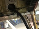
The not so pretty, but effective solution for me:
View attachment 131719

I didn't even know those Ferrules existed! I need to try one of those kits.


Glad you found it!For all of you that said "Sounds like a grounding issue", You appear to be correct.
Electrical problems are a giant pain. And I have a degree in EE so theoretically I know a few things.So let's say I didn't acquire an engine monitor and wanted the old gauge to work. How (Like I am a 5 year old) would I go about finding out what is the real problem?
And some smart person probably already told me this up there ^^^ but I have a cluster of gauges that appear to be getting a 12v power input on the ammeter gauge and the remaining 7 gauges are daisy chained down stream from that one, and there appears to be a ground on the last gauge that is connected to a sheet metal screw in the back of the gauge cluster housing.
Much like when I was in college playing Mortal Kombat where I would just mash buttons randomly not knowing what I was doing, I took the Multi meter and set it to ohms and put the red one on the 12v supply and touched random spots on the airframe and consistently got 6 Ohms. Is that good? bad? Sometimes I would win Mortal Kombat but I am not sure I am winning this.
I guess the question is what would someone that really knows the real special Mortal Kombat combos do to isolate where in the gauge chain the problem lies?
 And I spent far too much time examining wiring diagrams that show electrical connections, parts manuals that kinda showed where the wires physically went to some extent, and sitting there staring at and labeling things as I found them on the tractor itself and correlated them with the diagrams.
I installed my own CGR-30 combo, but it doesn't look that nice. Another advantage of an engine monitor is geeking out on all the data it records. It's easy to download and analyze. Also, you can have the alarm limits changed, such as CHT, by completing a form and having an A&P sign it and email it to EI.
Yup. Way back in post #13 I said all this:Now as I understand it, the + wire is connected to a new location and the - wire is grounded to the engine block and it is working beautifully.
A poor engine ground to the airframe can do it.
If the alternator is not well-grounded to the airframe, those electrons from it like to find other paths to the airframe, and one of those paths is through the oil temp sensor and to the gauge. This increases the electron flow through the gauge, spiking it.
In old airplanes, there are plenty of places where grounding is less than optimal, and so the new electric gauges in the old airplanes would read falsely high. The fix was a length of 20-gauge wire and some terminals to attach it to the engine crankcase as close as possible to the temp sensor, usually at an accessory case stud and nut, and then to the gauge's metal instrument case. This removed the voltage differential caused by bad grounding and the gauge would (usually) smarten up.