Intermittent ammeter discharging troubleshooting

ExParrot

Filing Flight Plan
Joined
Mar 8, 2023
Messages
9
Display Name

Display name:
ExParrot
Good morning,

Have a Cessna 182H that recently went through a panel upgrade last winter which included a GNC355, a GMA345, and two GI275s with vacuum system removal. For the first 30 or so hours after the upgrade everything was fairly trouble free, so issue might be totally unrelated.

Back in June I started noticing the ammeter jumping into discharge intermittently. Flickers down about an 1/8th to quarter inch into discharge then comes back to center. No circuit breakers are popped. This even happens with all electrical load save for 275s shed as well. So far we've checked wiring, then replaced voltage regulator with new Lamar unit, and then put in a refurbished alternator from aerotech. Sometimes the aircraft operates without any flickering of the ammeter into negative at all, but now the issue is back again.

Any additional troubleshooting tips would be very much welcome. Has anyone experienced this before?
 
Could it be an ammeter instrument issue? Do you have voltage monitoring/display also? If not and you have a cigarette outlet then there are [cheap] USB chargers you can plug in that also display the voltage. That might help to verify whether something is going on or not based on if you see a voltage change when the ammeter dips into discharge?
 
Could it be an ammeter instrument issue? Do you have voltage monitoring/display also? If not and you have a cigarette outlet then there are [cheap] USB chargers you can plug in that also display the voltage. That might help to verify whether something is going on or not based on if you see a voltage change when the ammeter dips into discharge?
I have a USB charger in the cigarette outlet that displays voltage and the voltage also drops with amps falling into discharge. Confirmed this as well with a multimeter connected to the terminal points behind the panel as well, so the load drop is real.
 
We had that once, for us it was a bad crimp on the alternator power cable where it connected to the alternator terminal
It could be that, or the cable is loose at the breaker. The cable from the starter contactor to the ammeter could be loose. It could be that the engine grounding is poor: loose or dirty ground strap at the engine, or at the engine mount or firewall, wherever it's grounded. Could even be the wire from the ALT switch to the regulator's "S" terminal is acting up. Or the feed to that switch from the bus. Or the ALT switch itself is old and its contacts are oxidized and is getting intermittent, though it's not terribly likely, as it carries very little current. The field wire between the regulator and alternator. Lots of places.

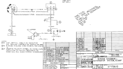
1691252540040.png


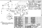
Edit: Let's add the rest of the circuit so one can see the ammeter's place in the system. It's #4:

1691269976097.png
 
Last edited:
It’s usually in the last place I look.
 
Update: we now have a new master switch, were good for about two flight hours, but the issue has returned, with a discharge happening even at minimum load for about 20 mins straight until we got into the pattern when charging picked up again. Replaced to date: voltage regulator (new Lamar), alternator (refurb), master switch.

At this point, the connectors going into the voltage regulator is my primary suspicion as it is the one connection we seem to touch with each attempted fix, the issue remains resolved for a couple hours, then comes back. I checked this by hand it feels snug. When it was off, I didn't see any obvious signs of failure on it.
 
were good for about two flight hours, but the issue has returned, with a discharge happening even at minimum load for about 20 mins straight until we got into the pattern when charging picked up again
Before you spend anymore money on parts, highly recommend you chase voltages a little more. But given it is "intermittant" a few questions:
1) Would you say the current problem is the same as your original problem in the OP? Or has it changed with the new parts?
2) Do you get a consistant 2 hour of flight before it happens?
3) Is the 20 minutes of discharge consistant? Or does it vary?
4) Does the ammeter have an internal shunt or external shunt?
5) Have duplicated this on the ground or does it only happen in flight?
6) What condition is the aircraft battery in? What is its static charge after a flight?
7) What is the alternator charging voltage?
I agree, I don't think the parts cannon is the solution here.

1. The problem is behaving the same as the original post/original problem though I would say is getting more severe, in that today was the first time I had a steady period of discharging

2. The rhythm has been troubleshoot, A&P suggests component, install, A&P test runs on ground no issue, I test fly for about an hour no issue. Go up for an hour flight a few days later, also no issue. Then either the next flight or flight after the issue crops back up

3. Today was the first time I've seen steady discharge, usually it jumps down to discharge for a second or two.

4. I'm don't know the answer to whether it is an internal or external shunt. I do know that I see the voltage at the cigarette lighter drop from 13.7 down to 12.0-12.3 (depending on load) when the ammeter goes into discharge.

5. Symptoms happen in ground and in air at pretty much any RPM.

6. After shutting down all avionics and lights with the engine off, the voltage at the cigarette lighter reads 12.2ish

7. With minimal load charging voltage as shown at the cigarette lighter is 13.7, I believe my A&P gets a tenth or two higher with a real multimeter attached to the bus on the ground.
 
The master switch only turns the master contactor on and off. If the master was intermittent, the contactor would open and the radios would die along with everything else. If the master was a split type, one side controls the regulator, switching it on and off. That could be a source of problems, but if that airplane has a low-voltage light, that light would illuminate.

This sounds like a loose connector related to the voltage regulator. Check that first schematic I posted earlier. Lots of places.

But a rebuilt alternator is no guarantee of eliminating the alternator as a problem. The rebuilders are often in the habit of putting way too much grease in the rear bearing, and it gets squeezed out when the rotor shaft goes into it and it ends up getting flung around and gets on the brushes and slip rings, creating a resistive sludge that drops the field current so that the ammeter shows a discharge. That mechanic should pull the field wire off the alternator or regulator and put an ohmmeter on the field terminal. See what the resistance says. It should be between 3 and 5 ohms, and should not change much if the propeller is moved. If it's high or jumps around, those slip rings and brushes are already contaminated and the only fix is to open the alternator up and clean everything, or send it back and tell them to do the job right as per the service manuals for that model.

I've had way too many "rebuilt" alternators apart for this very reason, from Kelly/Hartzell as well as smaller shops.
 
Last edited:
I see the voltage at the cigarette lighter drop from 13.7 down to 12.0-12.3
the voltage at the cigarette lighter reads 12.2ish
Start here. What brand battery and how old? A battery showing 12.2 after flight is basically dead if the reading is valid. And a dying battery will definitely cause issues with a charging system for various reasons.

First pull the battery or disconnect both cables and charge it for 24 hours with an appropriate charger per the OEM manual. Then disconnect the charger and let the battery rest for at least 4 hours. Then check its static or open voltage charge with a good digital meter. Anything less than 12.5-12.6 and your battery is technically unserviceable. The state of your battery will dictate the next move.
 
Last edited:
Start here. What brand battery and how old? A battery showing 12.2 after flight is basically dead if the reading is valid. And a dying battery will definitely cause issues with a charging system for various reasons.

First pull the battery or disconnect both cables and charge it for 24 hours with an appropriate charger per the OEM manual. Then disconnect the charger and let the battery rest for at least 4 hours. Then check its static or open voltage charge with a good digital meter. Anything less than 12.5-12.6 and your battery is technically unserviceable. The state of your battery will dictate the next move.
Gill battery is from 2016, and my memory didn't serve me correctly, it was up at 12.6 as measured at the cigarette lighter (again a couple tenths lower than actual and with the load from the Gi-275s powered on) today even after the flight with on and off charging. The battery has been strong to date, never had an issue cranking over the engine. Will see what it reads after a charge and rest.
 
Last edited:
Have you cleaned the battery connections, and the connection from battery to airframe ground?
 
Have you cleaned the battery connections, and the connection from battery to airframe ground?
Yes, connections were clean as well as airframe ground. Solid connections all around.
 
When troubleshooting an ammeter problem, one needs to know the charging circuit. If one doesn't, every suggestion is just guessing. Every single one. It's like trying to help some friend with his headache, and asking if he has clipped his toenails lately. Useless advice.

If the battery connections were bad enough to cause an ammeter to show discharge, starting would not happen. A discharge means that there is current flowing in the normal direction though the battery, and it is keeping electrical stuff alive. If it is not showing a charge, the battery and connections are not at fault. A charging indication means that electron flow is being forced backward through the battery to recharge it. If the battery was sulfated that ammeter would likely show a big charge, but the battery would not be doing its chemistry to store that electricity.

So the problem is that the alternator is not generating anything, or the regulator is not telling the alternator to get to work, or the alternator is unable to get the juice into the bus due to some rotten connection or a bad breaker or whatever.

Schematics in Post #5. They matter.
 
The battery has been strong to date, never had an issue cranking over the engine. Will see what it reads after a charge and rest.
Engine cranking ability isn't always a good indicator of battery health. A true capacity check will show it. A few more questions.

1) Was there any similar problem with the aircraft prior to your avionics upgrade?
2) You said the first 30 hours after the upgrade was "fairly trouble free". How do you define "fairly"?
3) And when you say "flickers down about an 1/8th to quarter inch into discharge", how many amps would you estimate that dimension equates to?

Since you've already checked the charging system wires and connections and the same problem happens on the ground, I think we should be able to figure out a few more checks once we know the battery health.
 
Yes, connections were clean as well as airframe ground. Solid connections all around.
Did you actually ohm out the ground post to airframe ground to be certain it's not the ground strap itself, or individually ring out the field, alt, switch and other wires at the regulator for high resistance, or just look at continuity?

We just had a problem where a strobe power pack quit. After checking there was good voltage at the hot, a good switch and a good ground and newly crimped connectors, a new power pack didn't work either. Very simple circuit. Turns out it was the power cable itself. Even with good continuity, the cable just could no longer carry the amps. After removing the old B+cable and replacing it, both old and replacement power packs worked. Visual inspection of the old cable showed no kinks, twists or chafes that would have suggested failure.

Kind of seems you're in a similar situation. You've replaced the major components, and you have the same problem with all load shed but the 275's. You've cleaned the bus connections and grounds, so logic suggests it must be the cable interconnects.
 
We just had a problem where a strobe power pack quit. After checking there was good voltage at the hot, a good switch and a good ground and newly crimped connectors, a new power pack didn't work either. Very simple circuit. Turns out it was the power cable itself. Even with good continuity, the cable just could no longer carry the amps. After removing the old B+cable and replacing it, both old and replacement power packs worked. Visual inspection of the old cable showed no kinks, twists or chafes that would have suggested failure.
Basic electricity. Ohm's Law defines this. The voltage at the powerpack should be checked with the B+ wire connected to the powerpack. Removing it and checking the voltage means that the multimeter, which only needs a few microamps to measure the voltage, will tell you that the voltage is good. But connect it to the load, and the truth comes out. Low or no voltage, because the several-amp draw of the load is impeded by a resistance somewhere, lowering the voltage at the load, and it doesn't work.

Mostly, it's a corroded crimp terminal somewhere along the way, or a bad switch or breaker that has oxidized contacts. Old airplanes are fun. One has to start measuring voltages between ground and all the positive points, with the master on and the load switched on. Check the bus voltage, then the breaker voltage at its output terminal, then the switch's input voltage, then its output voltage, then at any connector along the way. The defect will show up right away. If, for instance, the breaker has good voltage at it's buss connection but low voltage at it's output to the switch, that breaker is shot.

And a breaker is a lot cheaper than a new strobe powerpack.
 
To make the above clearer, imagine your lawn sprinkler hose with the sprinkler attached. You turn on the faucet, expecting the sprinkler to go to work, but it doesn't. You get the tiniest trickle and that's all. You disconnect the hose at the sprinkler and put a pressure gauge on the hose, and turn the faucet on. The gauge says the pressure is right up there, at 50 PSI or whatever. You reconnect the sprinkler and it still doesn't work. So you go buy a new sprinkler, thinking that the old one is defective, and the new one doesn't work either. A head-scratcher.

Eventually your kid points out that you parked your car on the hose, squashing it nearly flat so that only a tiny bit of water could get through. That tiny bit was enough to raise the pressure in the hose and make the gauge read normal, as long as there was no water flowing out of the hose. But that little bit could not do any sprinkling.

I used to use the water analogy in my Aircraft Systems class. The water pressure is the voltage that drives the flow. The water volume is the amperage. The kinked or squashed hose is an introduced resistance that reduces the flow to useless levels. The pressure times the volume is the amount of work that can be done by that water; in electricity, that's wattage. A fire truck has big wattage. It takes a lot of water from the hydrant, runs it though a pump that raises its pressure (voltage) so much that a fat stream of water (volume) can be sent high into the upper windows of a burning building.

And then I saw some blank stares from a few students. They had grown up in apartments and had never played with the sprinkler hose on a hot day.
 
Last edited:
I’ve occasionally wondered if you could get an airplane in the dark with the pertinent electrical systems running, and look at each wire & connector with some type of infrared device, maybe night vision goggles - to spot places making a bit too much heat.
 
After removing the old B+cable and replacing it, both old and replacement power packs worked.
Here's are a couple more options to test for voltage drops as mentioned by Dan. The way I mostly troubleshoot a system is to back probe at the device connector using the existing wires and the device for the load. It tests for voltage and drop at the same time. Care must be taken when back probing not to damage the connector or pin. There are probes specially designed to this and are cheap. Another method is to remove the device connector and apply a simulated load and check for voltage and drop. Light bulbs make for good load testers within certain amp ranges and can be match to the device load. And as a side note, light bulbs can also be used to T/S a short in the system, but that is for another time.
 
I think we have found our smoking gun: the crimp on the positive load wire coming off the Alternator (D-PB20 in post 5 I think). I checked this connector previously (admittedly, I do not have a good multimeter, a Fluke is on the shopping list), as did my A&P, nothing appeared or felt loose. After the charging system dropped out entirely a burn mark was now visible on the crimp insulation and the wire was pulled out of the connector by hand. Replaced the wire and connectors and we have stable charging again.

My take away from all this is I need to learn how to utilize a good multimeter here and run through the wiring systematically, would think we would have found this by finding a high resistance under load - I have no idea how you would physically do that without the engine running.

PXL_20230908_153133911.jpgPXL_20230908_153150743.jpg
 
2) You said the first 30 hours after the upgrade was "fairly trouble free". How do you define "fairly"?

Had a bad grease fitting for the prop where the check ball wouldn't seat properly and it slung grease all over the front of the airplane and coated the windscreen.

Took about 5 different USB sticks to figure out which type the GI-275 would actually talk to via the GSB 15 for updates.
 
would think we would have found this by finding a high resistance under load - I have no idea how you would physically do that without the engine running.
It depends. Chasing an intermittant indicating problem vs a bonifide charging problem that issue may have been missed. Regardless I've found way more faults via visual or tactile checks of wires and connections than with a meter. However, there are ways to substitute power or loads when troubleshooting just wires/connectors without running the engine.
 
FWIW - I wouldn't want to troubleshoot this sort of thing with a Fluke DVM. Maybe I'm old school but give me a simple cheap analog meter.
 
My take away from all this is I need to learn how to utilize a good multimeter here and run through the wiring systematically, would think we would have found this by finding a high resistance under load - I have no idea how you would physically do that without the engine running.
Well, one way is to drive the alternator with an electric motor. I did that once on a 172 that had alternator whine in the headsets and during transmit. With the alternator running, I took oscilloscope readings at various ground points and determined that the fault lay in the "portable" intercom that had been attached to the pedestal with screws, grounding the intercom case and attracting stray ground currents including alternator charging currents from the alternator case and ground cable. This is why most audio and mic jacks are insulated from the instrument panel.

I made a really sophisticated tool for trouble shooting charging system problems. It was a piece of half-inch plywood, maybe three inches by eight, with several screws in it and long wires soldered to those screws. The wires were attached at various points such as airframe ground, alternator field terminal, alternator output terminal, bus and so on. Sitting in the cockpit with the engine running and that "tool" in my lap I could take measurements between the ground screw and the others and get an idea of what was up. That bad crimp of yours would have shown up as a voltage differential between the alternator output terminal and the bus, implying that the cable or maybe the alternator output breaker was bad. The cable could have been isolated with moving the bus wire to the alternator breaker input terminal, removing the breaker as a possible offender. One other possibility would be the noise filter on the firewall; the charging current passed through it. The cable has crimps there, too.
 
Last edited:
FWIW - I wouldn't want to troubleshoot this sort of thing with a Fluke DVM. Maybe I'm old school but give me a simple cheap analog meter.
Yup. No need for expensive instruments here. The older analog gives a better indication of trends. I still use the one I bought over 50 years ago.
 
I think we have found our smoking gun: the crimp on the positive load wire coming off the Alternator (D-PB20 in post 5 I think). I checked this connector previously (admittedly, I do not have a good multimeter, a Fluke is on the shopping list), as did my A&P, nothing appeared or felt loose. After the charging system dropped out entirely a burn mark was now visible on the crimp insulation and the wire was pulled out of the connector by hand. Replaced the wire and connectors and we have stable charging again.

My take away from all this is I need to learn how to utilize a good multimeter here and run through the wiring systematically, would think we would have found this by finding a high resistance under load - I have no idea how you would physically do that without the engine running.

View attachment 120473View attachment 120475
Congrats! The blue deposits on the connector are usually a good clue. We had the same symptoms due to a break in the field wire that was intermittent. Every 40 years, pull the entire alternator regulator wiring harness, and examine it with a fine-tooth comb. Incidentally, on the new production aircraft, Cessna no longer bothers with shielded wire. Let your conscience be your guide!
 
Yes. But there are other like Triplett and AVO however Simpson is the popular one in the US.
I wouldn't want to troubleshoot this sort of thing with a Fluke DVM. Maybe I'm old school but give me a simple cheap analog meter.
FWIW: Digital and analog both have their pros and cons with some checks only an analog VOM can perform or give more accurate results. Having both covers most of the jobs except those where only a scope will work. Having a good digital meter with true manual range selection and a bar graph display usually can handle most troubleshooting to include the one above.
 
There's nothing wrong with using an oscilloscope for troubleshooting - especially if chasing noise like Dan Thomas above, but most shops don't have access to that sort of technology. And again most of the new ones are now digital. I have a 55 year old HP 130C analog scope that is perfect for this sort of monkey business.

I also have used the electric motor to drive a Lycoming-based alternator to chase diode whine and overvoltage dropout ala Dan Thomas.
 
but most shops don't have access to that sort of technology.
Scopes definitely have a place. But there are some decent single channel portable ones out there like the AES uScope for less than $200. If I were still active I'd definitely have one of these in my box.
 
Congrats!
Now you might inspect other crimps on the airplane, mainly ones that might have been re-done since factory.
Does the backside of this one show any dimple?
I wonder what did those slices?
 

Attachments

  • crimp.png
    crimp.png
    121.3 KB · Views: 6
I have an old dual-trace scope I bought from a TV repair shop that threw in the towel. Not exactly as "portable" as I might like, but great for finding a bad diode in an alternator bridge, or confirming clean square wave output from avionics. I think I paid like $25 for it.
 
1694383595180.png

This picture got me thinking. A 182H was built in about 1965. At that time, most light airplanes were still running generators, not alternators. They put out 25 or 35 amps. The alternators that came along a couple of years later were capable of 60 amps, and the output cable was upsized to carry it.

This cable above looks like 12 or maybe 10 gauge. The alternators used 8 gauge, to handle that amperage. If this airplane was converted from a generator to an alternator without upsizing the cable, further failures can be expected. Crimp terminals typically have more resistance than the cable itself, and this is the place that will get hot when overloaded.
 
This cable above looks like 12 or maybe 10 gauge. The alternators used 8 gauge, to handle that amperage. If this airplane was converted from a generator to an alternator without upsizing the cable, further failures can be expected. Crimp terminals typically have more resistance than the cable itself, and this is the place that will get hot when overloaded.

The old cable was 8 gauge and we did replace it with 8 gauge. This 182 as far as I can tell from the logs, history, and wiring diagrams came from the factory with an Alternator, not a generator, though the 60A breaker is still labeled Gen.
 
Back
Top