Ammeter not indicating

Ed Haywood

En-Route
Joined
Jul 12, 2020
Messages
3,636
Location
Tampa FL
Display Name

Display name:
Big Ed
As the title says. No charging flow shown when engine runs, even right after startup. No negative flow shown when all electrical components on and engine not running. Needle does not move at all.

Voltmeter at bus reads 14.3v with engine running, and 12.3v with engine off. I have flown 10 hours and several dozen engine starts since problem began, with no reduction in voltage.

Ammeter was installed new and run for the first time 2 months ago. It indicated correctly until about a month ago. It has an internal shunt.

I have checked all connections. Only thing I can think of is an internal gauge fault, perhaps with the shunt.

Before I return it, are there any other possibilities I should consider?
 
Last edited:
Add an “inop” sticker
Sorry I don’t know
Hoping someone else chimes in
 
Broken wire or loose connection, battery>ammeter>buss bar. Or bad gauge.
 
Before I return it, are there any other possibilities I should consider?
Are you only using those voltage readings to make this determination, or have you checked the voltage regulator, ammeter wiring, and ammeter itself to see where the problem might be?

And as a side note, having 12.3v on your battery at rest shows its not 100% either. Should be 12.6+ especially if you measured it just after engine shutdown.

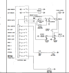
I have checked all connections and verified wiring is consistent with the wiring schematic, which is attached.

I believe I have sufficient information to determine that the ammeter is not correctly indicating current flow. When I turn on all electrical devices with the engine off, the needle stays in the zero position and does not move. I know current is reaching the bus because I can see lights on and devices powered up. The only electrical path from the battery to the bus is across the ammeter, so current must be flowing through the ammeter. The ammeter should be indicating negative current flow but is not.

I “think” the voltage readings tell me that the alternator is generating current and the battery is taking a charge. If that were not the case, battery voltage would have dropped after 10 hours of operation, and the battery would likely be dead after 25+ starts. If charging is happening, then current is flowing. The ammeter is the only current path from the alternator to the battery, so it should indicate that current flow, but it does not.

12.3v is at the bus. To get there from the battery, current must flow through the master solenoid, a 70 amp breaker, the ammeter, 15 feet of 8ga wire, and various terminals and crimps. Everything is brand new, but I would expect some resistance across that circuit, with consequent voltage drop. I’ll put a voltmeter on the battery today to verify I’m still getting 12.6v at the battery, like I was a few weeks ago.

So before I start throwing parts at it, starting with a new ammeter, what other diagnostics should I do?
 

Attachments

  • ACA elec print.jpg
    ACA elec print.jpg
    558.6 KB · Views: 12
Last edited:
So before I start throwing parts at it, starting with a new ammeter, what other diagnostics should I do?

In my opinion, you’ve done all you need to. Buy an ammeter and go from there.

Depending on battery type, 12.6v is about what I’d expect for a fully charged, open circuit voltage. Your 12.3v measurement at the bus is with some electrical devices turned on, thus dragging the battery down a bit. The only additional troubleshooting I’d be tempted to do, just to make 110% certain it is the ammeter would be to take a DMM and do a voltage check right at the battery while the engine is running to see what the voltage is there. During that process you might find that you want or need to adjust the voltage regulator in addition to replacing the ammeter.
 
You either put in a piece of junk or you have a bad connection. Since you checked your wires I'm thinking it's not a bad connection. If you are seeing 14+ volts while running, the battery is charging. I'd call whomever sold you the ammeter.
 
You either put in a piece of junk or you have a bad connection. Since you checked your wires I'm thinking it's not a bad connection. If you are seeing 14+ volts while running, the battery is charging. I'd call whomever sold you the ammeter.

If the bus is powered up it can’t be a bad connection; at least not one that is outside the meter itself since the original post says it has an internal shunt.
 
I believe I have sufficient information to determine that the ammeter is not correctly indicating current flow. When I turn on all electrical devices with the engine off, the needle stays in the zero position and does not move. I know current is reaching the bus because I can see lights on and devices powered up.
Bad ammeter.
12.3v is at the bus. To get there from the battery, current must flow through the master solenoid, a 70 amp breaker, the ammeter, 15 feet of 8ga wire, and various terminals and crimps. Everything is brand new, but I would expect some resistance across that circuit, with consequent voltage drop. I’ll put a voltmeter on the battery today to verify I’m still getting 12.6v at the battery, like I was a few weeks ago.
With the master on, and everything off, the only draw is the turn coordinator, and that only draws a small amount, certainly not enough to make a 0.3 volt drop between the the battery and bus. Some Citabrias had a pullable breaker for the TC so as to avoid damaging it during aerobatics. Pull it and then check the voltages.

Some encoders are connected directly to a radio breaker, so there might be some loading there. Depends how yours is wired. I don't like them connected like that, as they can get the big voltage spikes off the master and starter contactor coils when they are released. We had lots of encoder failures in airplanes wired like that.
 
So before I start throwing parts at it, starting with a new ammeter, what other diagnostics should I do?
Pull the ammeter and connect one terminal to the positive terminal on a battery. Connect the other ammeter terminal to one side of a minimum 12 volt landing light bulb. Connect the other side of the 12v light to the negative terminal on the same battery. If the ammeter needle does not move then its toast. If the needle does move then you have another problem to find.
12.3v is at the bus.
This is a separate issue to your ammeter problem. If your battery is at least 12.6v then 12.3v would be on the very high side of an acceptable voltage drop for your type aircraft. It can also be a sign of a possible electrical ground problem with its associated voltage drop. And everything being new doesn't necessarily mean everything is good. One bad new crimp or a painted ground lug can cause this also.

Fix your ammeter problem first, then see what your battery voltage is at the battery. Is the battery new also?

And just to note, you can have full voltage on a circuit (14.3v) but no current (amps). Hence the question on using just the voltage to troubleshoot.
 
Pull the ammeter and connect one terminal to the positive terminal on a battery. Connect the other ammeter terminal to one side of a minimum 12 volt landing light bulb. Connect the other side of the 12v light to the negative terminal on the same battery. If the ammeter needle does not move then its toast. If the needle does move then you have another problem to find.

Good idea, that makes perfect sense.

This is a separate issue to your ammeter problem.

Yes, agreed. I only provided the voltmeter readings as evidence that the ammeter is producing current.

Is the battery new also?

No, 2 years old, and has had a couple of deep discharge events so it is probably weak. But have not had any operational issues with the battery producing sufficient starting power, so as long as my flying is local, $500 for a new one is low on my budget priority.
 
Bad ammeter.
That's what I figured, but wanted to see if the old salts had any good tests to confirm. Will pull and test as Bell206 recommends.
With the master on, and everything off, the only draw is the turn coordinator, and that only draws a small amount, certainly not enough to make a 0.3 volt drop between the the battery and bus. Some Citabrias had a pullable breaker for the TC so as to avoid damaging it during aerobatics. Pull it and then check the voltages.
.3v drop was with all electrical devices on. Quick math tells me that is not unreasonable. Resistance of 15 feet of 8ga wire is 0.009 ohm, plus .001 ohm for 70A breaker. 20 amp load (AHI, engine monitor, gauges, LED anti-collision/nav/landing lights, radio, transponder, and USB charging port powering stratux) would produce .2 volt drop. Also, drop was not at the bus, it was at the end of the gauge and AHI circuits, which means another breaker, 4 feet of 18 or 20 gauge wire, and several more crimp terminals. 1 amp across a 5A breaker at .026 ohm and 4 feet of 20ga wire at .06 ohm is good for another .1v drop.

I'll use a DMM to check directly at battery and bus bar, with all devices but AHI off. Voltage drop is less of a concern for me than the ammeter.
 
If the bus is powered up it can’t be a bad connection; at least not one that is outside the meter itself since the original post says it has an internal shunt.

Pretty much what I said, but it still could be a bad connection. The power for the buss does not go through the ammeter. But I'm leaning toward an issue with the ammeter.
 
Pretty much what I said, but it still could be a bad connection. The power for the buss does not go through the ammeter. But I'm leaning toward an issue with the ammeter.

Yes, the power for the bus does go through the ammeter. That’s why I said that it is unlikely to be a bad connection. If it was a poor connection he’d had a lot of other problems as well.

About the only thing that doesn’t go through the ammeter is the starter motor.
 
Last edited:
Did some testing with DMM. Voltage across battery terminals is 12.99v with master off. Voltage with master on and AV-30 drawing 1A is 12.50v at battery, 12.46v at ammeter, and 12.42v at connection to landing light. Voltage drop from battery to bus is ~0.05v. Seems pretty good, no?

I didn’t have time to pull the ammeter and test. Probably gonna go ahead and order a new ammeter and throw it in when I get back from a trip in a few days.

So what causes an ammeter to go bad?
 
Last edited:
Something failed between the shunt and the meter windings..
 
Did some reading on ammeters. I assume shunt is pretty beefy, but moving coil could be more fragile. Maybe a victim of rough handling in shipment. Hopefully not vulnerable to acro. On a trip this week, so I'll go ahead and order a new meter so I don't lose any flying days when I get back. Not too expensive at $80 for a PMA instrument.
 
Clamp type ammeters are available for low prices nowadays, for example:


This can be clamped over your airplane's ammeter wires without having to disconnect anything so you can easily and non-invasively test it.

Make sure you get one that does DC; some cheaper ones are AC-only. And don't try to measure DC below one amp or so, these meters are quite sensitive to external fields.
 
The power for the buss does not go through the ammeter.
Oh boy. The typical Citabria wiring schematic:

1704737959193.png

Trace the power from the battery through the "battery relay" (master contactor) to the ammeter, through the ammeter to the bus, using the hot terminal of the alternator switch as a handy mounting. SO, when the alternator isn't running, the electron flow is from ground, through whatever is turned on, to the bus via switches and breakers, out of the bus to the ammeter (which will show a discharge) and thence to the battery and into ground again.

With the alternator operating and charging, the flow goes from ground, as before, through whatever is turned on, and none of the lights or radios sees any polarity change. It leaves the bus and goes to the alternator instead of the battery, and since the alternator's voltage is higher than the battery's, there is electron flow OUT of the battery, through the ammeter (which shows a charge now), and into the alternator, which pumps electrons into ground, where they go into the lights and radios and battery via their grounds.

The starter does not draw through the ammeter. 200+ amps would cook a 60-amp ammeter.

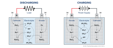
The reversed flow through the battery recharges it. The chemistry looks like this:

1704738627642.png

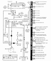
The Cessna airplanes use an alternator breaker in their circuits. Same principles apply:

1704739069128.png
 
Just a quick follow up: I replaced the ammeter and the new one works fine.
 
Back
Top