maverickps
Filing Flight Plan
- Joined
- Sep 19, 2020
- Messages
- 8
- Display Name
Display name:
maverickps
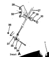
Where can I find the reference material or documentation that describes the proper way to connect the throttle cable to the throttle valve arm?
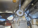
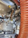
I had a mechanic swap in an overhauled carb and looks like he forgot either the castle nut, cotter pin, or both. During runup the throttle went full open as the cable came disconnected from the throttle. On opening the cowling we found the picture below. A different mechanic says the bolt/washer/nut were put on the wrong side to begin with and reversed them as shown in the second picture.
Just wondering where I can find a diagram that shows the correct placement of washers and nuts, thanks!